
Новини світу мікро- та наноелектроніки
The Smart Ring: Passing fad, or the next big health-monitoring thing?

The battery in my two-year-old first-gen Pixel Watch generally—unless I use GPS and/or LTE data services heavily—lasts 24 hours-plus until it hits the 15%-left Battery Saver threshold. And because sleep quality tracking is particularly important to me, I’ve more or less gotten in the habit of tossing it on the charger right before dinner, for maximum likelihood it’ll then robustly make it through the night. Inevitably, however, once (or more) every week or so, I forget about the charger-at-dinner bit and then, right when I’m planning on hitting the sack, find myself staring at a depleted watch that won’t make it until morning. First world problem. I know. Still…
Therein lies one (of several) of the key motivations behind my recent interest in the rapidly maturing smart ring product category. Such devices typically tout ~1 week (or more) of between-charges operating life, and they also recharge rapidly, courtesy of their diminutive integrated cells. A smart ring also affords flexibility regarding what watches (including traditional ones) I can then variously put on my wrist. And, as noted within my 2025 CES coverage:
This wearable health product category is admittedly more intriguing to me because unlike glasses (or watches, for that matter), rings are less obvious to others, therefore it’s less critical (IMHO, at least) for the wearer to perfectly match them with the rest of the ensemble…plus you have 10 options of where to wear one (that said, does anyone put a ring on their thumb?).
I’ve spent the last few months acquiring and testing smart rings from three leading companies: Oura (the Gen3 Horizon), Ultrahuman (the Ring AIR), and RingConn (the Gen 2). They’re left-to-right on my left-hand index finger in the following photo: that’s my wedding band on the ring finger  . The results have been interesting, to say the least. I’ll save per-manufacturer and per-product specifics for follow-up write-ups to appear here in the coming months. For now, in the following sections, I’ll share some general comparisons that span multiple-to-all of them.

An important upfront note: back in April, I learned that Finland-based Oura (the product category’s volume shipment originator, and the current worldwide market leader) had successfully obtained a preliminary ruling from the United States ITC (International Trade Commission) that both China-based RingConn and India-based Ultrahuman had infringed on its patent portfolio. The final ITC judgement, released on Friday, August 22 (three days ago as I write these words) affirmed that earlier ruling, blocking (in coordination with U.S. Customs and Border Protection enforcement) further shipments of both RingConn and Ultrahuman products into the country and, more generally, further sales by either company after a further 60 day review period ending on October 21. There’s one qualifier, apparently: retailers are allowed to continue selling past that point until their warehouse inventories are depleted.
I haven’t seen a formal response yet from RingConn, but Ultrahuman clearly hasn’t given up the fight. It’s already countersued Oura in its home country, also reporting that the disputed patent, which it claims combines existing components in an obvious way that renders it invalid, is being reviewed by the U.S. Patent and Trademark Office’s Patent Trial and Appeal Board.
We welcome the ITC’s recognition of consumer-protective exemptions and its rejection of attempts to block the access of U.S. consumers. Customers can continue purchasing and importing Ring AIR directly from us through October 21, 2025, and at retailers beyond this date.
What’s more, our software application and charging accessories remain fully available, after the Commission rejected Oura’s request to restrict them.
While we respectfully disagree with the Commission’s ruling on U.S. Patent No. 11,868,178, its validity is already under review by the USPTO’s Patent Trial and Appeal Board (PTAB) on the grounds of obviousness.
Public reporting has raised questions about Oura’s business practices, and its reliance on litigation to limit competition.
We are moving forward with confidence — doubling down on compliance while accelerating development of a next-generation ring built on a fundamentally new architecture. As many observers recognize, restricting competition risks fewer choices, higher prices, and slower innovation.
Ultrahuman remains energized by the road ahead, committed to championing consumer choice and pushing the frontier of health technology.
One perhaps-obvious note: the ITC’s actions only affect sales in the United States, not elsewhere. This also isn’t the first time that the ITC has gotten involved in a wearables dispute. Apple Watch owners, for example, may be familiar with the multi-year, ongoing litigation between Apple and Masimo regarding blood oxygen monitoring. Also, more specific to today’s topic, Samsung pre-emptively filed a lawsuit against Oura prior to entering the market with its Galaxy Ring in mid-2024, citing Oura’s claimed litigious history and striving to ensure that Samsung’s product launch wouldn’t be jeopardized by patent infringement lawsuits from Oura.
The lawsuit was eventually dismissed in March, with the judge noting a lack of evidence that Oura ever intended to sue Samsung, but Samsung is now appealing that ruling. And as I noted in recent Google product launch event coverage, this same litigious environment may at least partly explain why both Google/Fitbit and Apple haven’t entered the market…yet, at least.
Sizing prep is essentialBefore you buy a smart ring, whatever company’s device you end up selecting, I strongly advise you to first purchase a sizing kit and figure out what size you need on whatever finger you plan to wear it. Sizing varies finger-to-finger and hand-to-hand for every person, first and foremost. Not to mention that if the ring enhances your fitness, leading to weight loss, you’ll probably need to buy a smaller replacement ring eventually—the battery and embedded circuitry preclude the resizing that a jeweler historically would do—hold that thought.
Smart ring sizing can also vary not only from traditional ring measurements’ results, but also from company to company and model to model. My Oura and RingConn rings are both size 11, for example, whereas the Ultrahuman one is a size 10. Sizing kits are inexpensive…usually less than $10, with the purchase price often then applicable as credit against the subsequent smart ring price. And in the RingConn case, the kits are free from the manufacturer’s online store. A sizing kit is upfront money well spent, regardless of the modest-at-worst cost.

One key differentiator between manufacturers you’ll immediately run into involves charging schemes. Oura and Ultrahuman’s rings leverage close-proximity wireless inductive charging. Both the battery and the entirety of its charging circuitry, including the charging coil, are fully embedded within the ring. RingConn’s approach, conversely, involves magnetized (for proper auto-alignment)-connection contacts both on the ring itself and on the associated charger.

(Ultrahuman inductive charging)

(RingConn conventional contacts-based charging)
I’ve yet to come across any published pros-and-cons positioning on the two approaches, but I have theories. Charging speed doesn’t seem to be one of the factors. Second-gen-and-beyond Google Pixel Watches with physical contacts reportedly recharge faster than my wireless-based predecessor, especially after its firmware update-induced intentional slowdown. Conversely, I didn’t notice any statistically significant charge-speed variance between any of the smart rings I tested. Perhaps their diminutive battery capacities minimize any otherwise evident variances?
What about fluid-intrusion resistance? I could imagine that, in line with its usage with rechargeable electric toothbrushes operated in water exposure-prone environments:

inductive charging might make it possible, or at a minimum, easier from a design standpoint, to achieve higher IP (ingress protection) ratings for smart rings. Conversely, however, there’s a consumer cost-and-convenience factor that favors RingConn’s more traditional approach. I’ve acquired two chargers per smart ring I tested—one for upstairs at my desk, the other in the bathroom—the latter so I can give the ring a quick charge boost while I’m in the shower.
Were I to go down or (heaven forbid) up a size-or-few with an Oura or UltraHuman ring, my existing charger suite would also be rendered useless, since inductive charging requires a size-specific “mount”. RingConn’s approach, on the other hand (bad pun intended), is ring size-agnostic.
Speaking of RingConn, let’s talk about charging cases (and their absence in some cases). The company’s $199 Gen 2 “Air” model comes with the conventional charging dock shown earlier. Conversely, one of the added benefits (along with sleep apnea monitoring) of the $299 Gen 2 version is a battery-inclusive charging case, akin to those used by Bluetooth earbuds:

It’s particularly handy when traveling, since you don’t need to also pack a power cord and wall wart (conventional charger docks can also be purchased separately). Oura-compatible charging cases are, currently at least, only available from (unsanctioned-by-Oura, so use at your own risk) third parties and require a separate Oura-sourced dock.

And as for Ultrahuman, at least as far as I’ve found, there are only docks.
Internal and external form factorsIn addition to the aforementioned charging circuitry, there is other integrated-electronics commonality between the various manufacturers’ offerings (leading to the aforementioned patent infringement claim—if you’re Oura—or “obviousness” claim—if you’re Ultrahuman). You’ll find multi-color status LEDs, for example, along with Bluetooth and/or NFC connectivity, accelerometers, body temperature monitoring, and pulse rate (green) and oximetry (red) plus infrared photoplethysmography sensors.
The finger is the preferable location for blood-related monitoring vs the wrist, actually (theoretically at least), thanks to higher comparative aggregate blood flow density. That said, however, sensor placement is particularly critical on the finger, as well as particularly difficult to achieve, due to the ring’s circular and easily rotated form factor.
Most smart rings are more or less round, for style reasons and akin to traditional non-electronic forebears, with some including flatter regions to guide the wearer in achieving ideal on-finger placement alignment. One extreme example is the Heritage version of the Oura Gen3 ring:

with a style-driven flatter frontside compared to its Gen3 Horizon sibling:

Interestingly, at least to me, Oura’s newest Ring 4 only comes in a fully round style:

as well as in an expanded suite of both color and size options, all specifically targeting a growing female audience, which Ultrahuman’s Rare line is also more obviously pursuing (I hadn’t realized this until my recent research, but the smart ring market was initially male-dominated):
The Ring 4 also touts new Smart Sensing technology with 18 optical signal paths (vs 8 in the Gen3) and a broader sensor array. I’m guessing that this enhancement was made in part to counterbalance the degraded-results effects of non-ideal finger placement. To wit, look at the ring interior and you’ll encounter another means by which manufacturers (Oura with the Gen3, as well as RingConn, shown here) include physical prompting to achieve and maintain proper placement: sensor-inclusive “bump” guides on both sides of the backside inside:

Some people apparently find them annoying, judging from Reddit commentary and reviews I’ve read, along with the fact that Ultrahuman rings’ interiors are smooth, as well as the comparable sensor retraction done by Oura on the Ring 4. The bumps don’t bother me (and others); in contrast, in fact, I appreciate their ongoing optimal-placement physical-guidance assistance.
Accuracy, or lack thereofHow did I test all these rings? Thanks for asking. At any point in time, I had one on each index finger, along with my Pixel Watch on my wrist (my middle fingers were also available, along with my right ring finger, but their narrower diameters led to loose fits that I feared would unfairly throw off measurement results).
I rotated through my three-ring inventory both intra- and inter-day, also repeatedly altering which hand’s index finger might have a given manufacturer’s device on it. And I kept ongoing data-point notes to supplement my oft-imperfect memory.
The good news? Cardio- and pulmonary-related data measurements, including sleep-cycle interpretations (which I realize also factor in the accelerometer; keep reading), seemed solid. In the absence of professional medical equipment to compare against, I have no way of knowing whether any of the output data sets (which needed to be viewed on the associated mobile apps, since unlike watches, these widgets don’t have built-in displays…duh…) were accurate. But the fact that they all at least roughly matched each other was reassuring in and of itself.
Step counting was a different matter, however. Two general trends became increasingly apparent as my testing and data collection continued:
- Smart ring step counts closely matched both each other and the Pixel Watch on weekends, but grossly overshot the smart watch’s numbers on weekdays, and
- During the week, whatever ring I had on my right hand’s index finger overshot the step-count numbers accumulated by its left-hand counterpart…consistently.
Before reading on, can you figure out what was going on? Don’t feel bad if you’re stumped; I thank my wife’s intellect (which, I might add, immediately discerned the root cause), not mine (sloth-like and, standalone, unsuccessful), for sorting out the situation. On the weekends, I do a better job of staying away from my computer keyboard; during the week, the smart rings’ accelerometers were counting key presses as steps. And I’m right-handed, therefore leading to additional right-hand movement (and phantom step counts) each time I accessed the trackpad.
By the way, each manufacturer’s app, with varying breadth, depth, and emphasis, not only reports raw data but also interpretations of stress level and the like by combining and analyzing multiple sensors’ outputs. To date, I’ve generally overlooked these additional results nuances, no matter that I’m sure I’d find the machinations of the underlying algorithms fascinating. More to come in the future; for now, with three rings tested, the raw data was overwhelming enough.
Battery life and broader reliabilityAs I dove into the smart ring product category, I kept coming across mentions of claimed differentiation between their “health” tracking and other wearables’ “fitness” tracking. It turns out that, as documented in at least some cases, smart rings aren’t continuously measuring and logging data coming from a portion of their sensor suites. I haven’t been able to find any info on this from RingConn, whose literature is in general comparatively deficient; I’d welcome reader direction toward published info to bolster my understanding here. That said, the company’s ring was the clear leader of the three, dropping only ~5% of charge per day (impressively translating to nearly 3 weeks of between-charges operating life until the battery is drained).
Oura’s rings only discern heart rate variability (HRV) during sleep (albeit logging the base heart rate more frequently), “to avoid the daytime ‘noise’ that can affect your data and make it harder to interpret”. Blood oxygen (SpO2) sensing also only happens while asleep (I took this photo right after waking up, right before the watch figured out I’d done so and shut off):

Selective, versus continuous, data measurement has likely obvious benefits when it comes to battery life. That said, my Oura ring’s (which, like its RingConn counterpart, I bought already lightly used; keep reading) battery level dropped by an average of ~15% per day.
And Ultrahuman? The first ring I acquired only lasted ~12 hours until drained, and took nearly a day to return to “full”, the apparent result of a firmware update gone awry (unrecoverable in this case, alas). To its credit, the company sent me a replacement ring (and told me to just keep the existing one; stay tuned for a future teardown!). At about that same time, Ultrahuman also added another Oura-reminiscent and battery life-extending operating mode called “Chill” to the app and ring settings, which it also made the default versus the prior-sole “Turbo”:
Chill Mode is designed to intelligently manage power while preserving the accuracy of your health data. It extends your Ring AIR battery life by up to 35% by tracking only what matters, when it matters. Chill Mode uses motion and context-based intelligence to track heart rate and temperature primarily during sleep and rest.
More generally, keep in mind that none of these devices are particularly inexpensive; the RingConn Gen 2 Air is most economical at $199, with the Oura Ring 4 the priciest mainstream option at between $349 and $499, depending on color (and discounting the up-to-$2,200 Ultrahuman Rare…ahem…). A smart ring that lasts a few years while retaining reasonable battery life across inevitable cycle-induced cell degradation is one thing. One that becomes essentially unusable after a few months is conversely problematic from a reputation standpoint.
Total cost, and other factors to considerKeep in mind, too, that ongoing usage costs may significantly affect the total price you end up paying over a smart ring’s operating life. Ironically, RingConn is not only the least expensive option from an entry-cost standpoint but also over time; although the company offers optional extended warranty coverage for damage, theft, or loss, lifetime support of all health metrics is included at no extra charge.
On the other end of the spectrum is Oura; unless you pay $5.99/month or $69.99/year for a membership (first month free), “you’ll only be able to see your three daily Oura scores (Readiness, Activity, and Sleep), ring battery, basic profile information, app settings, and the Explore content.” Between these spectrum endpoints is Ultrahuman. Like RingConn, it offers extended warranties, this time including (to earlier comments) 2-year “Weight loss insurance”:
Achieved your weight loss goals? We’ll make resizing easy with a free Ultrahuman Ring AIR replacement, redeemable once during your UltrahumanX coverage period.
And, again, as with RingConn, although baseline data collection and reporting are lifetime-included, it also sells a suite of additional-function software plug-ins it calls PowerPlugs.
One final factor to consider, which I continue to find both surprising and baffling, is the fact that none of the three manufacturers I’ve mentioned here seems to support having more than one ring actively associated with an account, therefore, cloud-logging and archiving data, at the same time. To press a second ring into service, you need to manually delete the first one from your account first. The lack of multi-ring support is a frequent cause of complaints on Reddit on elsewhere, from folks who want to accessorize multiple smart rings just as they do with normal rings, varying color and style to match outfits and occasions. And the fiscal benefit to the manufacturers of such support is intuitively obvious, yes?
Looking back, having just crossed through 3,000 words, I’m sure glad I decided to split what was originally envisioned as a single write-up into a multi-post series I’ll try to get the RingConn and Ultrahuman pieces published ahead of that October 21 deadline, for U.S. readers that might want to take the purchase plunge before inventory disappears. And until then, I welcome your thoughts in the comments on what I’ve written thus far!
—Brian Dipert is the Editor-in-Chief of the Edge AI and Vision Alliance, and a Senior Analyst at BDTI and Editor-in-Chief of InsideDSP, the company’s online newsletter.
Related Content
- The Pixel Watch: An Apple alternative with Google’s (and Fitbit’s) personal touch
- The 2025 CES: Safety, Longevity and Interoperability Remain a Mess
- If you made it through the schtick, Google’s latest products were pretty fantastic
- Wireless charging: The state of disunion
The post The Smart Ring: Passing fad, or the next big health-monitoring thing? appeared first on EDN.
Mojo Vision raises $75m in Series B Prime funding round
A design guide for respiratory belt transducers

Curious about how respiratory belt transducers work—or how to design one yourself? This quick guide walks you through the essentials, from sensing principles to circuit basics. Whether you are a hobbyist, student, or engineer exploring wearable health technology, you will find practical insights to kickstart your own design.
Belly breathing, also known as diaphragmatic or abdominal breathing, involves deep inhalation that expands the stomach and allows the lungs to fully inflate. This technique engages the diaphragm—a dome-shaped muscle at the base of the lungs—which contracts downward during inhalation to create space for lung expansion and relaxes upward during exhalation to push air out.
In contrast, chest breathing (also called thoracic or shallow breathing) relies on upper chest muscles and produces shorter, less efficient breaths, limiting oxygen intake and often contributing to stress and tension. Belly breathing has been shown to lower heart rate and blood pressure, promote relaxation, and improve overall respiratory efficiency.
What if you could measure your breathing motion, capture it in real time, and receive meaningful feedback? A respiratory belt transducer offers a simple and effective solution. It detects changes in chest or abdominal diameter during breathing and converts that movement into a voltage signal, which can be recorded and analyzed to assess breathing patterns, rate, and depth.
First off, note that while piezoelectric, inductive, capacitive, and strain gauge sensors are commonly used in respiratory monitoring, this post highlights more accessible alternatives, namely conductive rubber cords and stretch sensors. These materials offer a low-cost, flexible solution for detecting abdominal or chest expansion, making them ideal for DIY builds, classroom experiments, and basic biofeedback systems.

Figure 1 A generic 2-mm diameter conductive rubber cord stretch sensor kit that makes breathing belt assembly easier. Source: Author
As observed, the standard 2-mm conductive rubber cord commonly available in the hobby electronics market exhibits a resistance of approximately 140 to 160 ohms per centimeter. This capability makes it suitable for constructing a respiratory belt that generates a voltage in response to changes in thoracic or abdominal circumference during breathing.
Next, fabricate the transducer by securely bonding the flexible sensing element—the conductive rubber cord—to the inner surface of a suitably sized fabric belt. It should then be placed around the body at the level of maximum respiratory expansion.
A quick hint on design math: in its relaxed state, the conductive rubber cord (carbon-black impregnated) exhibits a resistance of approximately 140 ohms per centimeter. When stretched, the conductive particles disperse, increasing the resistance proportionally.
Once the force is removed, the rubber gradually returns to its original length, but not instantly. Full recovery may take a minute or two, depending on the material and conditions. You can typically stretch the cord to about 50–70% beyond its original length, but it must stay within that range to avoid damage. For example, a 15-cm piece should not be stretched beyond 25–26 cm.
Keep in mind, this conductive rubber cord stretch sensor does not behave in a perfectly linear way. Its resistance can change from one batch to another, so it’s best used to sense stretching motion in a general way, not for exact measurements.
To ensure accurate signal interpretation, a custom electronic circuitry with a sensible response to changes in cord length is essential; otherwise, the data will not hold water. The output connector on the adapter electronics should provide a directly proportional voltage to the extent of stretch in the sensing element.
Frankly, this post doesn’t delve into the mechanical construction of the respiratory belt transducer, although conductive rubber cords are relatively easy to use in a circuit. However, they can be a bit tricky to attach to things, both mechanically and electrically.
The following diagram illustrates the proposed front-end electronics for the resistive stretch sensor (definitely not the final look). Optimized through voltage scaling and linearization, the setup yields an analog output suitable for most microcontroller ADCs.

Figure 2 The proposed sensor front-end circuitry reveals a simplistic analog approach. Source: Author
So, now you have the blueprint for a respiratory belt transducer, commonly known as a breathing belt. It incorporates a resistive stretch sensor to detect changes in chest or abdominal expansion during breathing. As the belt stretches, the system produces an analog output voltage that varies within a defined range. This voltage is approximately proportional to the amount of stretch, providing a continuous signal that mirrors the breathing pattern.
Quick detour: A ratiometric output refers to a sensor output voltage that varies in proportion to its supply voltage. In other words, the output signal scales with the supply itself, so any change in supply voltage results in a corresponding change in output. This behavior is common in unamplified sensors, where the output is typically expressed as a percentage of the supply voltage.
Before wrapping up, I just came across another resistive change type strain sensor worth mentioning: GummiStra from Yamaha. It’s a rubber-like, stretchable sensor capable of detecting a wide range of small to large strains (up to twice in length), both statically and dynamically. You can explore its capabilities in detail through Yamaha’s technology page.

Figure 3 GummiStra unlocks new use cases for resistive stretch sensing across wearables, robotics, and structural health monitoring. Source: Yamaha
We will leave it there for the moment. Got your own twist on respiratory belt transducer design? Share your ideas or questions in the comments.
 T. K. Hareendran is a self-taught electronics enthusiast with a strong passion for innovative circuit design and hands-on technology. He develops both experimental and practical electronic projects, documenting and sharing his work to support fellow tinkerers and learners. Beyond the workbench, he dedicates time to technical writing and hardware evaluations to contribute meaningfully to the maker community.
Related Content
- Key design considerations, future of IoT sensors
- High-Performance Design for Ultrasound Sensors
- Improving Sensor to ADC Analog Interface Design
- Transducer Options for Safe, Precise Current Sensing
- Vacuum transducer features cost-effective OEM integration
The post A design guide for respiratory belt transducers appeared first on EDN.
ROHM’s SiC MOSFETs in mass production in Schaeffler’s inverter brick
Top 10 Reinforcement Learning Applications and Use Cases
One of the most intriguing areas of machine learning is reinforcement learning (RL), in which agents interact with their surroundings and acquire the best behaviors through trial and error. RL is perfect for resolving complicated, real-world issues because, in contrast to classical supervised learning, it flourishes in dynamic, uncertain environments. Reinforcement learning is reshaping how machines make decisions, driving innovation in areas such as autonomous vehicles and tailored healthcare solutions. The top 10 notable applications that highlight the strength and adaptability of reinforcement learning will be explored in this article.
- Autonomous Vehicles
RL empowers autonomous vehicles to make intelligent decisions in real time, enabling them to navigate complex and ever-changing environments—such as congested traffic or unpredictable road conditions with greater precision and adaptability.
- Predictive Maintenance
With reinforcement learning, predictive maintenance could figure out when a machine is most likely to break down, to get it fixed bait time. With that, the RL agents comprehend when equipment failure might occur by learning from past reports and further optimizes maintenance scheduling to reduce downtime and save repair costs.
- Personalized Recommendations
Reinforcement learning is employed by streaming platforms such as Netflix, and e-commerce giants such as Amazon, to customize recommendations, adapting to the evolving preferences of a user, and learning which content or products an individual is most likely to engage with.
- Healthcare Treatment Planning
RL is revolutionizing personalized medicine to assist clinicians in determining the best therapeutic strategy. It can also be used for radiation therapy, drug dose optimization, and robotic-assisted surgeries to achieve better outcomes at lower risks.
- Energy Management in Grids
Reinforcement learning(RL) helps optimize energy consumption in smart buildings and grids. By learning patterns of usage and environmental conditions, the systems adjust heating, cooling, and lighting to avoid wastage. Such measures reduce costs.
- Supply Chain and Inventory Optimization
RL-based systems help retailers and logistics companies maintain inventory levels, forecast demand, and optimize delivery routes, lowering operational costs while increasing levels of customer satisfaction.
- Robotics and Automation
In robotics, RL allows machines to acquire the skills required to perform complex tasks such as walking, grasping, and assembling objects. Manufacturing, space, and domestic robots rely on these types of skills.
- Financial Trading and Portfolio Management
RL systems allow creation of trading and portfolio management strategies adapted to the fluctuations of markets. They may improve risk management, increase returns, and support decision-making in volatile environments.
- Drone and Aerospace Navigation
With reinforcement learning, it is possible for drones and space vehicles to autonomously plan routing, collision avoidance, and adaptiveness to environmental changes. This feature is highly potential in scenarios where human intervention is limited or impossible.
- Natural Language Processing (NLP)
In NLP, the chatbot and virtual assistant are fine-tuned by reinforcement learning methods to produce a more coherent and context-aware response. It is also applied in such areas as training translation, summarization, and sentiment analysis models.
Conclusion:
Reinforcement Learning is more than just a theoretical concept it’s a transformative force across industries. Its ability to learn from interaction and adapt to change makes it uniquely suited for solving problems that traditional algorithms struggle with. As reinforcement learning (RL) continues to advance, it is expected to unlock increasingly ground-breaking applications that redefine the capabilities of machines. Whether one is a researcher, developer, or simply an intrigued observer, RL remains a dynamic and promising field that merits close attention and exploration.
The post Top 10 Reinforcement Learning Applications and Use Cases appeared first on ELE Times.
How TVS Electronics is Transforming Digital India with “Make in India” AIDC
In the fast-paced world of digital transformation, Automatic Identification and Data Capture (AIDC) has moved beyond just scanning barcodes it is now driving intelligent business outcomes powered by AI, IoT, 5G, and cloud. At the forefront of this transformation is Mr. Chakravarthy Balaji, Chief Business Officer and Vice President Products & Solutions Group (PSG Business) at TVS Electronics (TVSE).
With nearly two decades of leadership at TVSE, Mr. Balaji has played a pivotal role in reshaping the company’s growth trajectory from finance operations to leading large-scale product innovations.
In this exclusive interview with ELE Times, Mr. Balaji shares insights on how AIDC is evolving with next-gen technologies, the role of cloud-native analytics, and how TVS Electronics is positioning itself to lead the next wave of Industry 4.0 adoption in India. Excerpts:
ELE Times: How is Advanced AIDC evolving with AI, IoT, and Industry 4.0?
C. Balaji: Advanced AIDC is shifting from simple data capture to intelligent data interpretation. With AI, IoT, and Industry 4.0, it now enables predictive insights, real-time visibility, and autonomous decision-making across industries.
ELE Times: What role do cloud-native integration and real-time analytics play in driving digital transformation through AIDC?
C. Balaji: Cloud-native AIDC ensures scalability and agility, while real-time analytics converts raw data into actionable insights. Together, they drive faster decisions, process transparency, and end-to-end digital transformation.
ELE Times: What makes TVS Electronics’ ‘Make in India’ AIDC solutions stand out technologically?
C. Balaji: Our AIDC solutions are rugged, reliable, and designed for Indian conditions while meeting global standards. With launches like industrial-grade label printers, scanners, fixed scanners, and enterprise mobile computers such as HS65 and T1 Pro, we combine strong R&D, local innovation, and pan-India service support to deliver true “Make in India” excellence.
ELE Times: What role is TVS Electronics playing in leveraging AIDC to drive digital transformation across industries?
C. Balaji: TVS Electronics is enabling enterprises across retail, logistics, manufacturing, and healthcare with end-to-end AIDC solutions. We act as a solutions partner, aligning technology with business outcomes and industry digital roadmaps.
ELE Times: Which emerging technologies (AI, IoT, 5G, cloud) are most critical for the future of AIDC-led transformation?
C. Balaji: AI, IoT, 5G, and cloud are converging to redefine AIDC. Together, they transform AIDC from a data enabler into a decision enabler, powering the next wave of digital enterprises.
ELE Times: How is TVS Electronics preparing its products and services to address the next wave of digital transformation needs?
C. Balaji: We are expanding our portfolio with industrial-grade label printers, advanced scanners, fixed-position devices, and mobility solutions like HS65 and T1 Pro. Alongside, we are building partnerships in AI, IoT, and cloud to deliver future-ready, scalable, and customer-centric solutions for Industry 4.0.
The post How TVS Electronics is Transforming Digital India with “Make in India” AIDC appeared first on ELE Times.
Silanna UV’s next-gen SF2 230nm far-UVC LED doubles radiant intensity
Lotus Microsystems and EDOM Technology Form Strategic Distribution Partnership to Expand Presence Across APAC
Distribution Partnership to Expand Presence Across APAC
Lotus Microsystems ApS, a power management solutions company, and EDOM Technology, one of the Top 10 Global Distributors, jointly announced the signing of a strategic distribution agreement for the Asia-Pacific region.
This collaboration combines Lotus Microsystems’ innovative power management solutions with EDOM Technology’s extensive distribution network, strong field application engineering (FAE) force, and deep market expertise. The partnership is designed to accelerate customer adoption, deliver superior technical support, and strengthen the presence of both companies across the fast-growing APAC markets.
Power and thermal management are crucial aspects of electronic design, especially in the rapidly developing computing, networking, and IoT markets. Effective thermal management ensures that devices operate within a safe temperature range, optimizing performance and extending their operational life. Lotus Microsystems’ work on high-efficiency power modules supports more sustainable computing by reducing energy losses and improving overall power usage effectiveness.
“This partnership with Lotus Microsystems allows us to bring differentiated and forward-looking solutions to our customers in the APAC region. We see great potential in Lotus Microsystems’ technology and are confident it will contribute to the success of our ecosystem.”
— Jeffrey Yu [CEO of EDOM Technology]
“We are delighted to partner with EDOM Technology, a recognized leader in distribution across Asia. This agreement marks an important step in our global expansion, enabling Lotus Microsystems to better serve customers in key APAC markets with the strong support and capabilities that EDOM provides.”
— Hans Hasselby-Andersen [CEO of Lotus Microsystems]
The post Lotus Microsystems and EDOM Technology Form Strategic Distribution Partnership to Expand Presence Across APAC appeared first on ELE Times.
Cars That Talk: Reimagining driving with RADAR, LIDAR and Smart Connectivity
By: STMicroelectronics
Vehicles across the continent are increasingly shifting from ‘passive’ to ‘active’ safety features with the aim of preventing crashes from happening at all – particularly since an EU mandate came into effect. One part of the shift towards active safety is the evolution of in-cabin driver and occupant monitoring systems. These systems combine critical data within one central intelligence network to create a better picture of human behavior in the car and contributing to a safer driving experience.
But the other – perhaps more crucial part – will be in the connected infrastructure that supports drivers on the road. Technologies like RADAR (Radio Detection and Ranging) and LiDAR (light detection and ranging) are set to detect traffic, perceive potential obstacles and understand the environment outside the vehicle. With these technologies combined, cars will be able to ‘talk’ to the environment around them – with the potential to usher-in a new era of connectivity and road safety.
RADAR vs LiDARLet’s dive into these technologies and how they work together. Both RADAR and LiDAR enable accurate depth sensing. RADAR uses radio waves to provide long-range object detection in even the most adverse weather conditions. LiDAR emits laser light pulses to offer high precision and detail for 3D mapping. By emitting radio waves that bounce off objects and return to the sensor, RADAR systems can detect how far away an object is, the relative speed of that object, the direction of its movement and – depending on resolution and signal processing – the size and shape of that object.
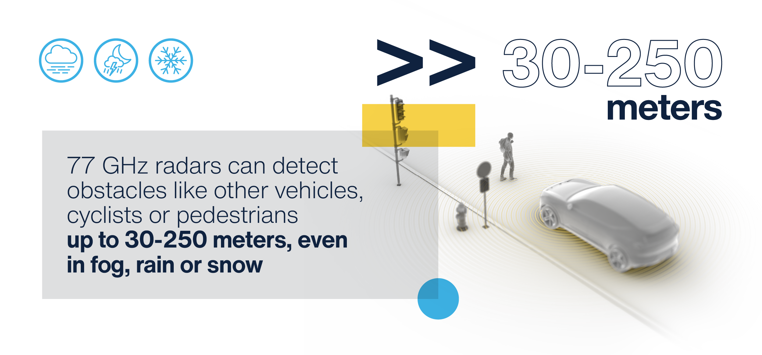
With this information, vehicles are better equipped to identify potentially dangerous situations and prevent crashes. Radar technology, for example, can detect if the car in front suddenly slows down and as the gap between vehicles decreases, automatic emergency braking systems can be deployed. On a technical level, automotive radar solutions typically use 24 GHz or 77 GHz bands, balancing range and resolution requirements. While 24 GHz radars are used in Advanced Driver Assistance Systems (ADAS) to provide safety features such as blind-spot detection, rear cross traffic alerts and collision avoidance, 77 GHz radars can detect obstacles like other vehicles, cyclists or pedestrians in the 30 to 250 meter range, even in low visibility conditions like fog, rain and snow.
By comparison, LiDAR systems emit a series of short bursts of light that reflect off objects and surfaces before returning to the sensor. The “time of flight” data is used to calculate the distance to an object and create a dense collection of 3D points, mapping out a detailed 3D model. This precise object detection and classification is ideal for more complex or even semi-autonomous driving scenarios, where distinguishing between pedestrians, vehicles, and road edges is crucial. LiDAR is typically more precise than RADAR, however LiDAR is more susceptible to distortion or lower performance in fog or rainy conditions.
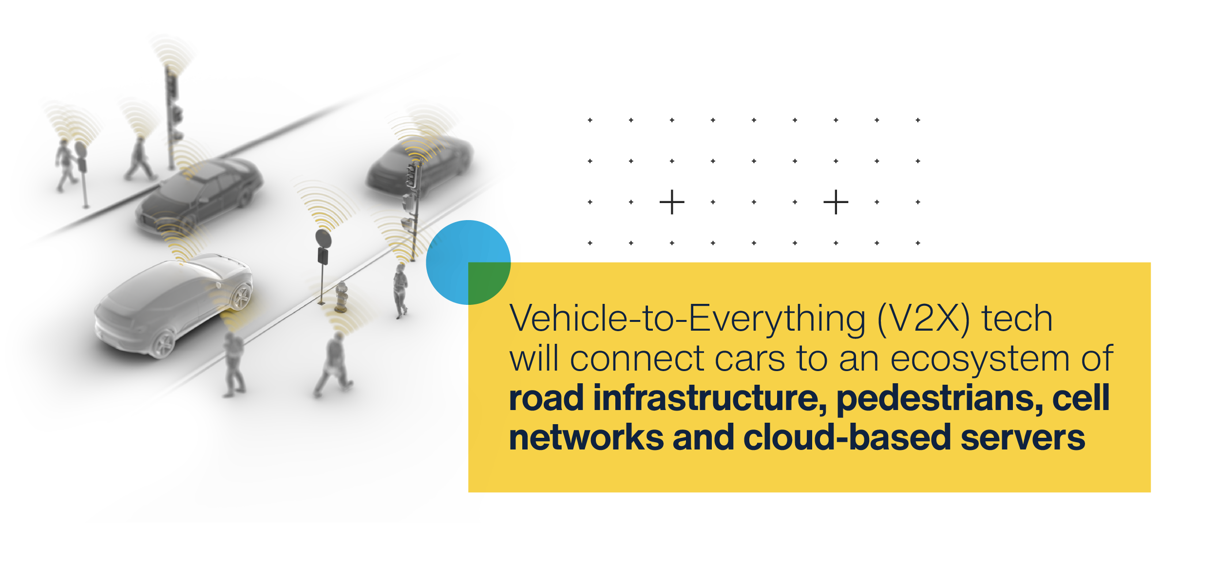
The V2X layerMany modern vehicles combine RADAR and LiDAR to formulate a more detailed and complete picture of the vehicle’s surroundings – and enables a future of Vehicle-to-Everything (V2X) communication. V2X refers to an intelligent ecosystem where cars are just one piece of the puzzle. With V2X communication, vehicles, road infrastructure, pedestrians and cellular networks or cloud-based services can exchange information in real-time.
The symbiotic relationship between these technologies is certainly exciting – with the potential to improve journeys and reduce road accidents. Environmental sensors would monitor road surface conditions. When moisture levels build up, this data can be communicated to adaptive road signs to automatically reduce speed limits. Thinking of congestion, traffic sensors can measure vehicle volumes and speeds, feeding into traffic signals so green lights can be extended when necessary to reduce traffic jams on the roads. This technology is yet to be deployed on a massive scale, but is already being tested in cities across the United States, China and Portugal – and the momentum will only increase as the benefits are felt by road users.
A connected ecosystem of carsV2X technology transforms connected cars into mobile sensors. Each car will collect anonymized data about road conditions, hazards, and traffic patterns – and also hard braking events and airbag deployments to areas of poor visibility – to benefit all road users without compromising driver privacy. In this world, authorities could apply automatic speed limitations based on real-time data from vehicle clusters – by sending a warning to the driver about a pothole, or the car auto-adjusting for those conditions.
Pedestrians would also be safer. If a vehicle’s sensors may not “see” a child on a bike about to emerge from behind a parked car, a smart roadside unit equipped with V2X technology may catch it from another vantage point to warn nearby drivers so they can slow down or even trigger automatic braking.
Data governance in the V2X ageQuestions of data privacy and accountability are also emerging as V2X capabilities continue to scale. Who is accountable if a software update introduces a safety flaw? And should anonymized safety data – from near-miss incidents to driver behavior patterns – be shared between automotive manufacturers to improve system-wide learning?
Safety improvements need to be balanced with the diminishing role of human agency in the vehicle. Though we are some years from fully autonomous vehicles, the shift is underway to reduce the margin for human error on the roads. Yet if drivers are less engaged or less able to intervene quickly if an incident arises, it could paradoxically increase risk in situations where manual override becomes necessary. The evolution of increasingly connected and autonomous vehicles must go hand-in-hand with transparency, good data stewardship, and appropriate human oversight if the industry is to build trust in a V2X-enabled future.
Driving 2.0With RADAR, LIDAR and V2X technology, vehicles are on track to become one node in a much larger and more intelligent ecosystem. They will be able to make sense of the world around them, detecting and interacting with the road, other vehicles and their wider external environment so evasive action can be taken early to avoid collisions.
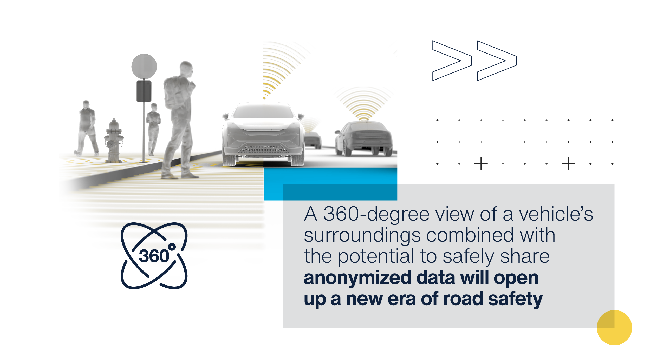
A comprehensive 360-degree view of a vehicle’s surroundings combined with the potential to safely share anonymized data will enable a new era of road safety.
The post Cars That Talk: Reimagining driving with RADAR, LIDAR and Smart Connectivity appeared first on ELE Times.
Antenna Innovations Come in Sizes Ranging from a Stamp to a School Bus
Mitsubishi Electric selected for JAXA’s Space Strategy Fund to develop solar cells for Japanese satellites
Lumentum offering $1.1bn in convertible notes due in 2032
Western Australia’s Nimy appoints technical advisor on extractive metallurgy
DIY AMP board
 |
I will complete to make Input board and Vol control, LED EQ [link] [comments] |
Packing More Brains Into Buds: Multi-Feature AI on Tiny Silicon
A temperature-compensated, calibration-free anti-log amplifier
 The typical anti-log circuit
The basic anti-log amplifier looks like the familiar circuit of Figure 1.

Figure 1 The typical anti-log circuit has uncertainties related to the reverse current, Is, and is sensitive to temperature.
Wow the engineering world with your unique design: Design Ideas Submission Guide
The approximate equation for V0 given in Figure 1 comes from the Ebers-Moll model. A more advanced model employed by many modern spice simulators, such as LTspice, is the Gummel-Poon model, which I won’t discuss here. It suffices for discussions in this Design Idea (DI) to work with Ebers-Moll and to let simulations benefit from the Gummel-Poon model.
The simple Figure 1 circuit is sensitive to both temperature and the value of Is. Unfortunately, the value and limits of Is are not specified in datasheets. Interestingly, spice models employ specific parametric values for each transistor, but still say nothing about the limits of these values. Transistors taken from different sections of the same silicon wafer can have different parametric values. The differences between different wafers from the same facility can be greater yet and can be even more noticeable when those from different facilities of the same manufacturer are considered. Factor in the products of the same part number from different manufacturers, and clear, plausible concerns about design repeatability are evident.
Addressing temperature and Is variationsThere’s a need for a circuit that addresses these two banes of consistent performance. Fortunately, the circuit of Figure 2 is a known solution to the problem [1].

Figure 2 This circuit addresses variations in both temperature and Is. Key to its successful operation is that Q1a and Q1b constitute a matched pair, taken from adjacent locations on the same silicon wafer. Operating with the same VCEs is also beneficial for matching.
It works as follows. Given that Q1a and Q1b are taken from adjacent locations on the same silicon wafer, their characteristics (and specifically Is) are approximately identical (again, Is isn’t spec’d). And so, we can write that:
 It’s also clear that:

Additionally,
![]()
So:
![]()
Therefore:
![]()
Substituting Ic expressions for the two VBEs,

And here’s some of the circuit’s “magic”: whatever their value, the matched Is’s cancel! From the properties of logarithms,

Again, from the properties of logarithms:

Exponentiating, substituting for the Ic’s, and solving for V0:

Note that Vi must be negative for proper operation.
Improving temperature compensationLet’s now turn our attention to using a thermistor to deal with temperature compensation. Those I’m used to dealing with are negative temperature coefficient (NTC) devices. But they’ll do a poor job of canceling the “T” in the denominator of Equation (1). Was there an error in Reference [1]?
I exchanged the positions of R3 and the (NTC) thermistor in the circuit of Figure 2 and added a few resistors in various series and parallel combinations. Trying some resistor values, this met with some success. But the results were far better with the circuit as shown when a positive temperature coefficient (PTC) was used.
I settled on the readily available and inexpensive Vishay TFPT1206L1002FM. These are almost perfectly linear devices, especially in comparison to the highly non-linear NTCs. Figure 3 shows the differences between two such devices with resistances of 10 kΩ at 25°C. It makes sense that a properly situated nearly linear device would do a better job of canceling the linear temperature variation.

Figure 3 A comparison of a highly non-linear NTC and a nearly linear PTC.
To see if it would improve the overall temperature compensation in the Figure 2 circuit, I considered adding a fixed resistor in series with the TFPT1206L1002FM and another in parallel with that series combination.
Thinking intuitively that this three-component combination might work better in the feedback path of an inverting op amp whose input was another fixed resistor, I considered both the original non-inverting and this new inverting configurations. The question became how to find the fixed resistor values.
The argument of the exponent in Equation (1) (exclusive of Vi) provides the transfer function H(T, <resistors, PTC>), which would be ideally invariant with temperature T (with Th1 suitably modified to accommodate the series and parallel resistors).
For any given set of resistor values, the configurations apply some approximate, average attenuation α to the input voltage Vi. We need to find the values of the resistors and of α such that for each temperature Tk over a selected temperature range (I chose to work with the integer temperatures from -40°C to +85°C inclusive and used the PTC’s associated values), the following expression is minimized:

Excel’s Solver was the perfect tool for this job. (Drop me a note in this DI’s comments section if you’re interested in the details.)
The winning resultThe configurations were found to work equally well (with different value components.) I chose the inverter because it allows Vi to be a positive voltage. Figure 4 shows the winning result. The average value α was determined to be 1.1996.

Figure 4 The simulated circuit with R2a, R2b, and R3 chosen with the help of Excel’s Solver. A specific matched pair of transistors has been selected, along with values for resistors R1 and Rref, and a voltage source Vref.
For Figure 4, Equation (1) now becomes approximately:

The circuit in Figure 4 was simulated with 10° temperature steps from -40°C to +80°C and values for Vi of 100 µV, 1 mV, 10 mV, 100 mV, 1 V, and 6 V. These V0 values were divided by those given by Equation (2), which are the expected results for this circuit.
Over the industrial range of operating temperatures and more than four orders of magnitude of input voltages, Figure 5 shows a worst-case error of -4.5% / +1.0%.

Figure 5 Over the industrial range of operating temperatures and over 4.5 orders of magnitude of input voltages from 100 µV to 6 V, the Figure 4 circuit shows a worst-case error of better than -5.0% / + 1.0%. V0 ranges from 2.5 mV to 3 V.
BonusWith a minor addition, this circuit can also support a current source output. Simply split Figure 4’s R1 into two resistors in series and add the circuit of Figure 6.

Figure 6 Split R1 of Figure 4 into R1a and R1b; also add U4, Rsense, and a 2N5089 transistor to produce a current source output.
CaveatsWith all of this, the simulation does not account for variations between the IS’s of a matched pair’s transistors; I’m unaware of a source for any such information. I’ve not specified op-amps for this circuit, but they will require positive and negative supplies and should be able to swing at least 1-V negative with respect to and have a common-mode input range that includes ground. Bias currents should not exceed 10 nA, and sub-1 mV offset voltages are recommended.
Temperature compensation for anti-log ampExcel’s Solver has been used to design a temperature-compensation network for an anti-log amplifier around a nearly linear PTC thermistor. The circuit exhibits good temperature compensation over the industrial range. It operates within a signal range of more than three orders of magnitude. Voltage and current outputs are available.
References
- Jain, M. K. (n.d.). Antilog amplifiers. https://udrc.lkouniv.ac.in/Content/DepartmentContent/SM_6aac9272-bddd-4108-96ba-00a485a00155_57.pdf
Related Content
- Gain control
- Why modulate a power amplifier?—and how to do it
- Power amplifiers that oscillate—deliberately. Part 1: A simple start.
- Log and limiting amps tame rowdy communications signals
- Mutant op amp becomes instrumentation amp
The post A temperature-compensated, calibration-free anti-log amplifier appeared first on EDN.
Nagoya spinoff Photo electron Soul’s GaN-based e-beam technology targets semiconductor inspection & metrology
Tata–Merck MoU to Accelerate Chip Manufacturing Infrastructure in India
Tata Electronics Private Limited has signed a strategic Memorandum of Understanding (MoU) with Merck, a global leader in science and technology, to accelerate the development of India’s semiconductor ecosystem. The agreement, finalized, underscores a joint commitment to building robust capabilities in materials, fabrication, and supply chain infrastructure.
Under the partnership, Merck will prepare a full suite of advanced solutions for Tata Electronics, including high-purity electronic materials, advanced gas and chemical delivery systems, and turnkey fabrication infrastructure services. Merck’s AI-enhanced Material Intelligence solutions will also aid operations at Tata’s Semiconductor Fabrication Plant in Dholera, Gujarat.
The partnership encompasses more than just the transfer of technology. Merck will provide guidance on safety and production excellence practices and grant access to Athinia, a secure data analytics platform that enables collaboration at scale. The contract also foresees the establishment of local warehouses, the development of raw material supply chain, and talent development programs, all aimed at bolstering India’s position in the semiconductor sector in the world.
Tata Electronics has promised to invest ₹91,000 crore ($11 billion) in creating the Dholera semiconductor fabrication plant, the first of its kind in India. Once operational, the fab will manufacture chips for applications ranging from automotive and mobile devices to artificial intelligence and advanced computing, catering to both domestic and international markets.
This partnership is viewed as a major step in furthering the goals of the India Semiconductor Mission, establishing Merck and Tata Electronics as important figures in determining the future of high-tech production in the nation.
The post Tata–Merck MoU to Accelerate Chip Manufacturing Infrastructure in India appeared first on ELE Times.
UP Electronics Policy Draft to Boost Smartphone and Electronics Manufacturing
The Uttar Pradesh government has introduced a draft policy aimed at strengthening electronics and smartphone manufacturing in the state, with a particular focus on the Noida region. The initiative is part of the state’s broader goal of becoming a $1 trillion economy by 2030.
The draft policy titled “UP Electronics Component Manufacturing Policy 2025” has a goal of providing an ecosystem to nurture domestic and international investors. A variety of incentives, such as capital investment subsidies, stamp and electricity duty waivers, and participation interest grants are proposed to gain more participants.
The state’s IT and electronics department confirmed that the policy was approved by the cabinet in September 2025 and has been made effective retrospectively from April 1, 2025.
The policy aims to achieve $50 billion worth of electronics production within the next five years. Electronics production from U.P. is expected to grow, attracting serious investment, creating massive employment, and cementing the state’s position as a major player in India’s U.P. electronics manufacturing is expected to grow multi-fold within that period.
With Noida as a confirmed centre for electronics and smartphone production, the policy is expected to enhance the state’s role in global supply chains supporting the greater vision of India as a hub for electronics manufacturing.
The post UP Electronics Policy Draft to Boost Smartphone and Electronics Manufacturing appeared first on ELE Times.
Semicon India 2025: PM Modi Says India’s Semiconductor Revolution Will Shape Global Future
Prime Minister Narendra Modi inaugurated Semicon India 2025, positioning India as a rising powerhouse in the global semiconductor industry. Addressing the summit, he said the world now looks to India not only as a trusted partner but as a future leader in chip innovation.
“Oil has been referred to as black gold in the semiconductor industry, but chips are the digital diamonds,” Modi said, highlighting India’s determination to become a full-stack semiconductor nation. Even though we started our trip later than others, we are now unstoppable. The world’s largest revolution will soon be made possible by India’s smallest chip.
Under the Atmanirbhar Bharat vision, the Prime Minister underlined that India’s efforts go beyond chip production and instead concentrate on creating a comprehensive semiconductor ecosystem that boosts competitiveness and self-reliance.
He further elaborated on the Indian semiconductor plan by connecting the dots with India’s stronger economic output. “GDP figures released for the first quarter indicate that India’s GDP is growing at a remarkable 7.8 percent. The growth is seen in every sector of the economy,” he said, putting semiconductor development into the picture of the national economy.
The summit came after Modi’s trip to Japan, where he visited Tokyo Electron Miyagi Ltd., a notable company in semiconductor technology. He explained the complementary relationship between Japan’s advanced technology and India’s nascent semiconductor manufacturing ecosystem and implied that there is more collaboration from other countries to come.
India’s semiconductor market, estimated to be worth between $45 and $50 billion in FY2024–2025, is expected to more than double to $100–110 billion by 2030, according to industry projections presented at the event. Together with international collaborations and regulatory backing, this quick growth is anticipated to solidify India’s position as one of the world’s most important chip-making destinations.
The post Semicon India 2025: PM Modi Says India’s Semiconductor Revolution Will Shape Global Future appeared first on ELE Times.
Сторінки


![[link]](https://i.redd.it/ywj6pyvxezmf1.jpeg)